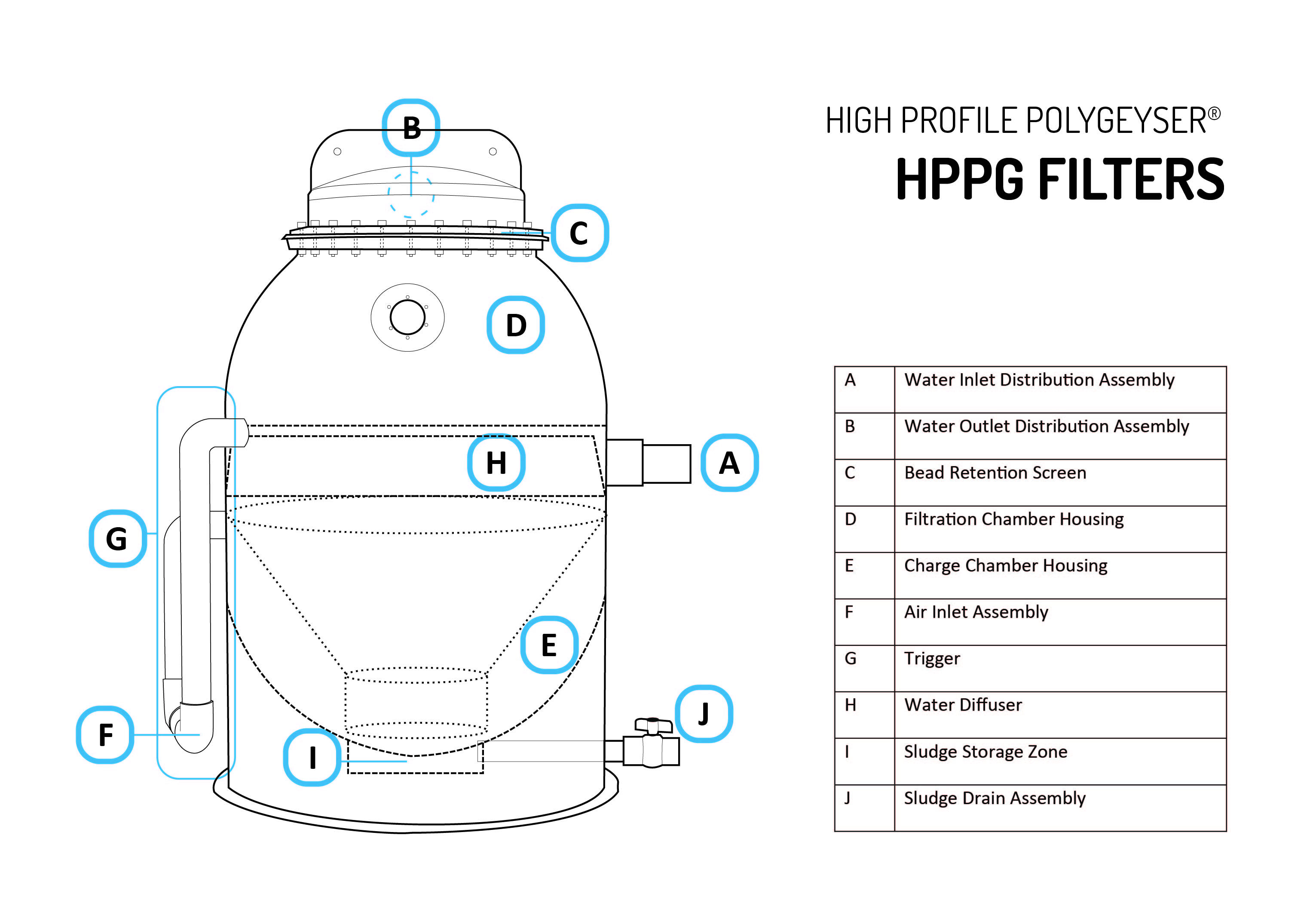
High Profile PolyGeyser Installation Assembly
HPPG Major Components
| Descriptor | Function | Comment | |
|---|---|---|---|
| A | Inlet | Directs flow into filter via the diffuser | |
| B | Screen | Passes water while retaining the beads in the filter | |
| C | Outlet | Directs the filtered water into the return lines | Multiple outlets are generally used for airlift models to lower water velocity and hydraulic friction |
| D | Bead Bed | Captures suspended solids while providing surface area for biological processes, such as nitrification, used to restore water to a pristine condition | The beads float to form tightly packed granular bed ideal for physical and biological filtration. Beads are typically 2-3 mm in diameter |
| E | Charge Chamber | The air tight cone defines the charge chamber while forming a conduit for water transmission into and out of the charge chamber | In this design series, the charge chamber is wrapped around the centralized conduit which re-suspends and aerates sludge during each backwash event |
| F | Air Inlet | Slowly fills the charge chamber with air | Air is added at a slow rate so that it takes a few hours to fill the charge chamber |
| G | Trigger | Catastrophically releases air from the charge chamber once it is filled | |
| H | Diffuser | Redirects the incoming water beneath the bead bed | Hydraulically designed to minimize turbulence that may erode the bed. |
| I | Sludge Basin | Provides for temporary sludge storage | The sludge that is released from the bead bed during a backwash settles out of the cone and charge chamber that can be removed periodically as a thick sludge through the sludge outlet |
| J | Sludge Outlet | Facilitates the removal for thickened sludge from the unit. | Sludge is typically concentrated to 10,000-20,000 mg/L in the HPPG series. |
| Cap | Directs flow from the screen to the Outlet pipe(s) | The cap assembly also includes gaskets that seal the screen to the filter hull |
